Application Sector
Capacitor Solutions for EV Charging Equipment
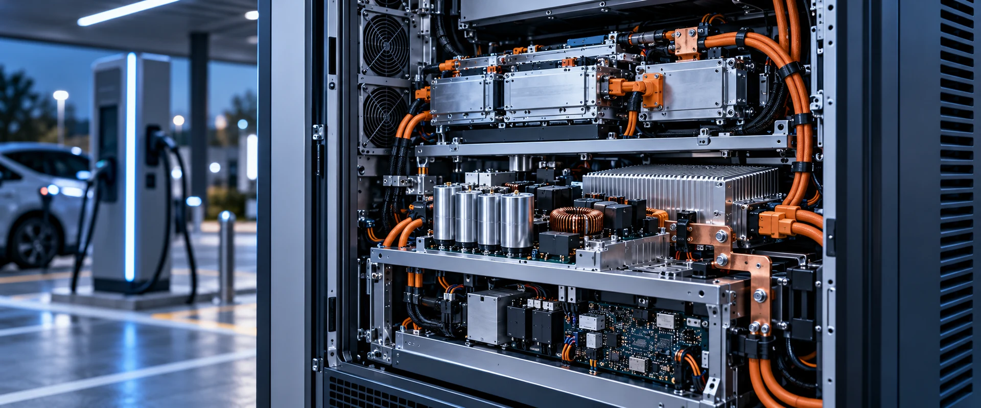
Charging equipment is a chain of power conversion stages. Input rectification and power-factor correction feed a high-voltage DC bus, and isolated DC-DC modules convert that bus to what the vehicle asks for. Each stage exposes capacitors to a different mix of voltage, ripple and temperature.
The demanding positions are the bulk and DC-link ones: they combine high DC voltage with continuous ripple current, usually inside a thermally managed cabinet that is expected to run for years between service visits.
The Yunrui catalogue does not state charging-station applications for any series. The products referenced below are listed because the catalogue names them for switching power supplies, inverter circuits and large power supply circuits, which is what those stages are. They may be considered for power-conversion applications depending on circuit requirements; nothing here claims a charging-standard or grid approval.
Design challenges
Application Challenges in EV Charging
Power conversion stages in charging equipment create these design pressures.
High DC bus voltage
Rectified mains and boosted buses operate at voltages where rating margin and, where relevant, series or bank arrangements have to be decided early in the design.
Continuous ripple current
Bulk positions in these stages see ripple continuously while charging sessions last. Internal heating from ripple is often the practical limit, not the ambient conditions.
Thermal management of the cabinet
Power cabinets are cooled but not cold. The temperature around the capacitors depends on airflow design and on how close they sit to the switching semiconductors.
Long expected service interval
Charging infrastructure is expected to stay in service for years. Endurance at operating temperature should be compared against that interval.
Selection dimensions
Capacitor Requirements for EV Charging
At these power levels, six dimensions decide the shortlist.
Rated voltage and margin
Decide the working bus voltage, add margin for mains variation and transients, and check whether the rating has to be achieved with a single part or a bank.
Capacitance for the bus
Value follows hold-up and bus ripple requirements; the physical size then feeds back into the mechanical design.
Ripple current capability
Check the ripple rating for the actual position and for the temperature it operates at, since ripple ratings are temperature dependent.
Operating temperature and endurance
Compare the endurance figure with the expected operating profile of the installation rather than with a nominal temperature alone.
Terminal type and mounting
Snap-in terminals suit board-mounted assemblies; screw terminals suit high-current and large-can assemblies that bolt into a bus structure.
Serviceability
Consider how the capacitor is accessed and replaced, since this influences both the mechanical design and the economic choice.
Layer A and B
Recommended Product Types
Recommendations below are given on two levels. Product types reflect where the catalogue supports power-conversion use generally; the named series carry a catalogue statement about switching power supplies, inverters or large power supply circuits, and are offered here with that limitation restated.
Snap-in electrolytic capacitors
Board-mounted bulk capacitance for power conversion assemblies, where snap-in terminals replace through-hole leads for larger can sizes.
Screw terminal electrolytic capacitors
Large-can parts for high-capacitance positions assembled with bolted terminals, typical of larger power supply and conversion equipment.
Relevant series
These three series are named in the catalogue for the circuit types used in conversion equipment. They may be considered for power-conversion applications depending on circuit requirements; the catalogue does not state charging use.
CS Series
Catalogue names this series for switching power supplies and inverter circuits; verified for a 160V to 450V DC rating with 7,000 hours endurance at 105 degC. Suited to high-voltage bus positions depending on circuit requirements.
LS Series
Catalogue names this series for switching power supplies and inverter circuits; verified for a rated voltage range up to 550V DC with 3,000 hours endurance at 105 degC.
SR Series
Screw terminal construction named in the catalogue for large power source, uninterruptible power supply and frequency converter circuits; verified for a 25V to 450V DC rating at 105 degC.
Two further snap-in series with longer endurance figures and one additional screw terminal series exist in the catalogue for the same circuit types. No statement about charging standards, grid codes or type approval is made here because our documentation does not contain one.
No certification relating to charging standards, grid connection or vehicle approval is claimed on this page.
Circuit positions
Typical Use Cases
Representative positions inside charging equipment, described by circuit function.
Input rectification and bulk stage
Where rectified mains is smoothed and held up before further conversion.
DC-link position
Bus capacitance between the input stage and the isolated DC-DC modules.
DC-DC module output filtering
Filtering on the vehicle-side output of the conversion stage.
Auxiliary supply for control electronics
Lower-voltage rail feeding control, metering and communication boards inside the charger.
Power cabinet assembly
Mechanically bolted high-capacitance positions where screw terminal construction and bus-bar layout are part of the design.
Engineering checklist
Selection and Reliability Considerations
What to check before shortlisting a capacitor for this equipment class.
- Establish the bus voltage including worst-case mains variation before choosing a rating.
- Check the ripple current rating at the temperature the part will actually run at.
- Decide single-part versus bank arrangement from voltage margin and capacitance needs together, and review balancing if banks are used.
- Check terminal type against the assembly method and the current path.
- Review how the part is replaced in the field before freezing the mechanical design.
- Final capacitor selection should be confirmed against the specific electrical, thermal and mechanical requirements of the application.
Next step
Relevant Products and Series
Published links into the product structure. Every link below goes to a live page.
Relevant product families
Relevant categories
Request for quotation
Need help selecting a capacitor for your application?
Tell us what the circuit actually needs and we will answer with comparable part options rather than a generic brochure.
- Application and equipment type
- Working voltage including excursions
- Required capacitance and ripple current
- Operating temperature at the capacitor position
- Required lifetime or service interval
- Mounting and board-space constraints
Guizhou Yunrui Electronic Technology Co., Ltd. was established in 2018 and operates a 68,000 m2 production facility with 300+ production lines, more than 4,000 product models, 25 intellectual property rights and a supply capacity of approximately 15 million pieces per day, under ISO 9001 and ISO 14001 certified systems.